Theory and Methodology
The two-step procedure is a common approach for multiphysics full-core nuclear reactor analysis. These steps are:
Step 1: Generate neutron group constant data with a lattice or full-core reactor model on a high-fidelity, continuous/fine-energy neutronics software at various reactor states.
Step 2: Use an intermediate-fidelity, computationally cheaper neutronics software with the neutron group constant data to perform multiphysics reactor analysis.
Moltres falls under Step 2 of the two-step procedure. Moltres solves the conventional multigroup neutron diffusion and delayed neutron precursor equations. The precursor equations include precursor drift terms to account for precursor movement under molten salt flow. Moltres is built on the MOOSE finite element framework, enabling highly flexible and scalable reactor simulations.
Multigroup Neutron Diffusion
The neutron diffusion equation is an approximation to the Boltzmann transport equation, and is derived by taking the zeroth and first moment with respect to , the direction of neutron travel. A full derivation of the diffusion equation will not be presented here for conciseness. Importantly, when taking the first moment of the transport equation the angular flux is assumed to be linearly anisotropic. The approximations reduce the phase space through the elimination of angular dependence, but the resulting equation also has reduced fidelity when compared to the transport equation, particularly in regions where the neutron flux has strong angular dependence. A non-exhaustive list of regions in which the neutron flux strongly depends on angle is near material interfaces between materials with highly dissimilar neutronic properties, within strong absorbers, and within near-void regions. As a deterministic method, the neutron diffusion method also requires discretization of the continuous energy dependence into energy groups consisting of non-overlapping, finite energy ranges across the entire energy spectrum. This energy discretization creates a system of equations referred to as the multigroup neutron diffusion equations:
The delayed neutron precursor distributions are governed by:
Notably, there are two production terms of neutrons, the prompt fission source and delayed neutron precursor decay source. The first term describes the neutrons immediately born from fission, and the second term describes the neutrons born from the radioactive decay of neutron-emitting radionuclides, commonly called delayed neutron precursors. The multigroup neutron diffusion equations are generally impossible to solve analytically for realistic problems and are therefore typically solved with numerical methods. Moltres utilizes the Finite Element Method (FEM) capabilities provided by the MOOSE framework. In FEM, the spatial domain is discretized into finite mesh elements and the time dependence is modeled through discrete time steps and time integration methods.
Table 1: Terms in multi-group neutron diffusion equation and their associated kernels
| Term in Multi-Group Diffusion Equation | Associated Kernel | Definition of Term |
|---|---|---|
| NtTimeDerivative | Time rate of change of energy group g | |
| GroupDiffusion | Streaming term of energy group g | |
| SigmaR | Removal from energy group g | |
| InScatter | In-scattering into energy group g | |
| CoupledFissionKernel | Prompt fission neutron source | |
| DelayedNeutronSource | Delayed fission neutron source |
Table 2: Terms in delayed neutron precursor equation and their associated kernels
| Term in Delayed Precursor Equation | Associated Kernel(s) | Definition of Term |
|---|---|---|
| ScalarTransportTimeDerivative | Time rate of change of precursor population | |
| PrecursorSource | Production of precursor from fission | |
| PrecursorDecay | Loss of precusors due to radioactive decay | |
| DGCoupledAdvection, DGFunctionConvection, DGConvection | Advection of the precursors |
For the advective term in the delayed neutron precursor equation, , there are three kernels. DGCoupledAdvection is used when the velocity is a variable in the simulation, DGFunctionConvection is used when the velocity is a function, and DGConvection is for when the velocity is constant.
Heat Transfer and Fluid Flow
Moltres compiles with the MOOSE Navier-Stokes and Heat Transfer modules for flow modeling capabilities by default. Moltres couples with these modules natively because they are all built on the MOOSE framework.
Past work with Moltres have modeled incompressible salt flow and temperature advection-diffusion with the INS or INSAD implementations of the Navier-Stokes equations (Peterson et al., 2018). Coupling with the compressible or finite volume implementations within the Navier-Stokes module are likely possible, but have not been demonstrated yet.
For turbulence modeling, Moltres has a Spalart-Allmaras (SA) turbulence model (Spalart and Allmaras, 1992) implementation with streamline-upwind Petrov-Galerkin (SUPG) stabilization. On balance the SA model is a complete (does not require prior knowledge of the actual turbulence behavior) and computationally efficient turbulence model for approximating wall-bounded turbulent flows. The SA model implementation in Moltres is compatible with the INSAD implementation only. Additionally, Moltres contains turbulent diffusion physics kernels for temperature and the delayed neutron precursors.
The SA model in Moltres follows the (SA-noft2-R) implementation as described on the NASA Turbulence Modeling Resource website. The term is togglable using the use_ft2_term input parameter (false by default). Moltres' implementation solves for the modified dynamic viscosity which can be easily obtained using to convert to as follows:
where
and the constants are:
We performed simple verification and validation tests of the SA model in Moltres using reference problems for channel, pipe, and backward-facing step flow. The Moltres test dataset is available on Zenodo. The following subsections show plots comparing results from Moltres to reference data from literature.
Turbulent Channel Flow Verification Test
The channel flow test is based on the direct numerical simulation (DNS) of turbulent channel flow with by Moser et al. (1999). The Moltres input file for this problem may be found in moltres/problems/2023-basic-turbulence-cases/channel-flow/.
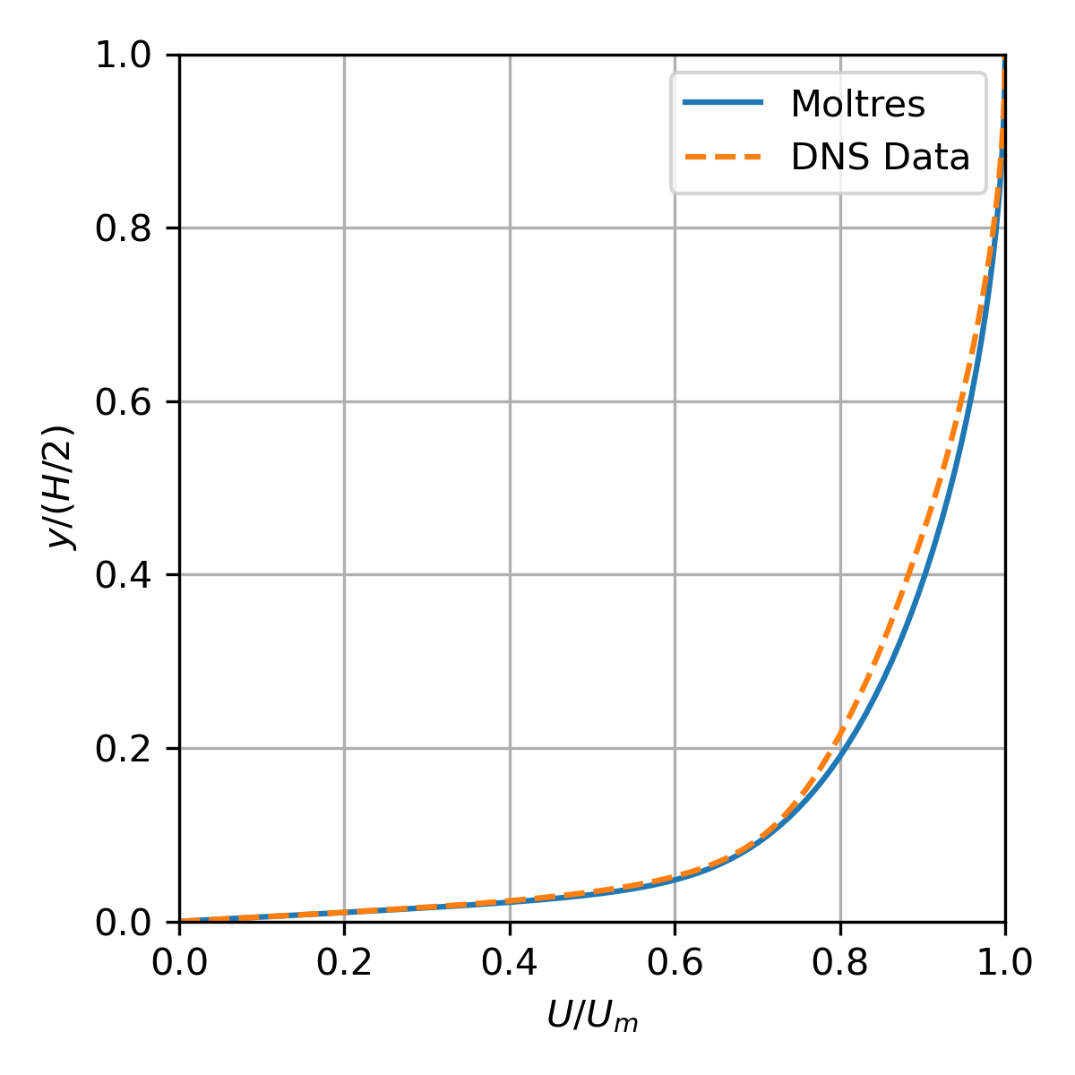
Figure 1: Normalized velocity distribution across the channel.
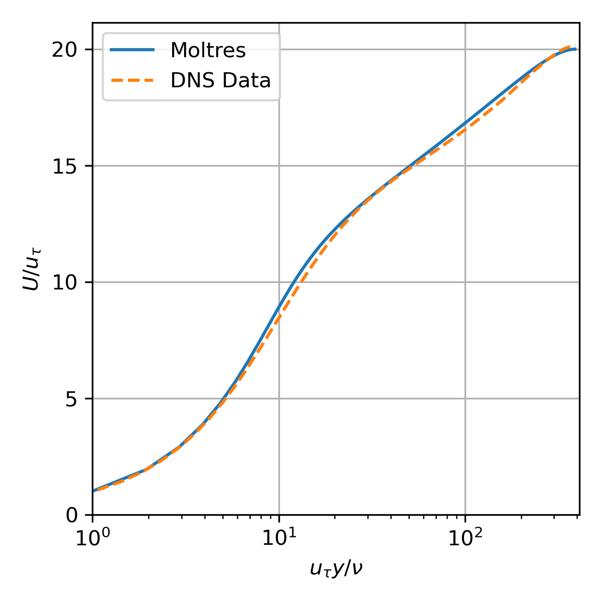
Figure 2: Dimensionless velocity vs dimensionless wall distance.
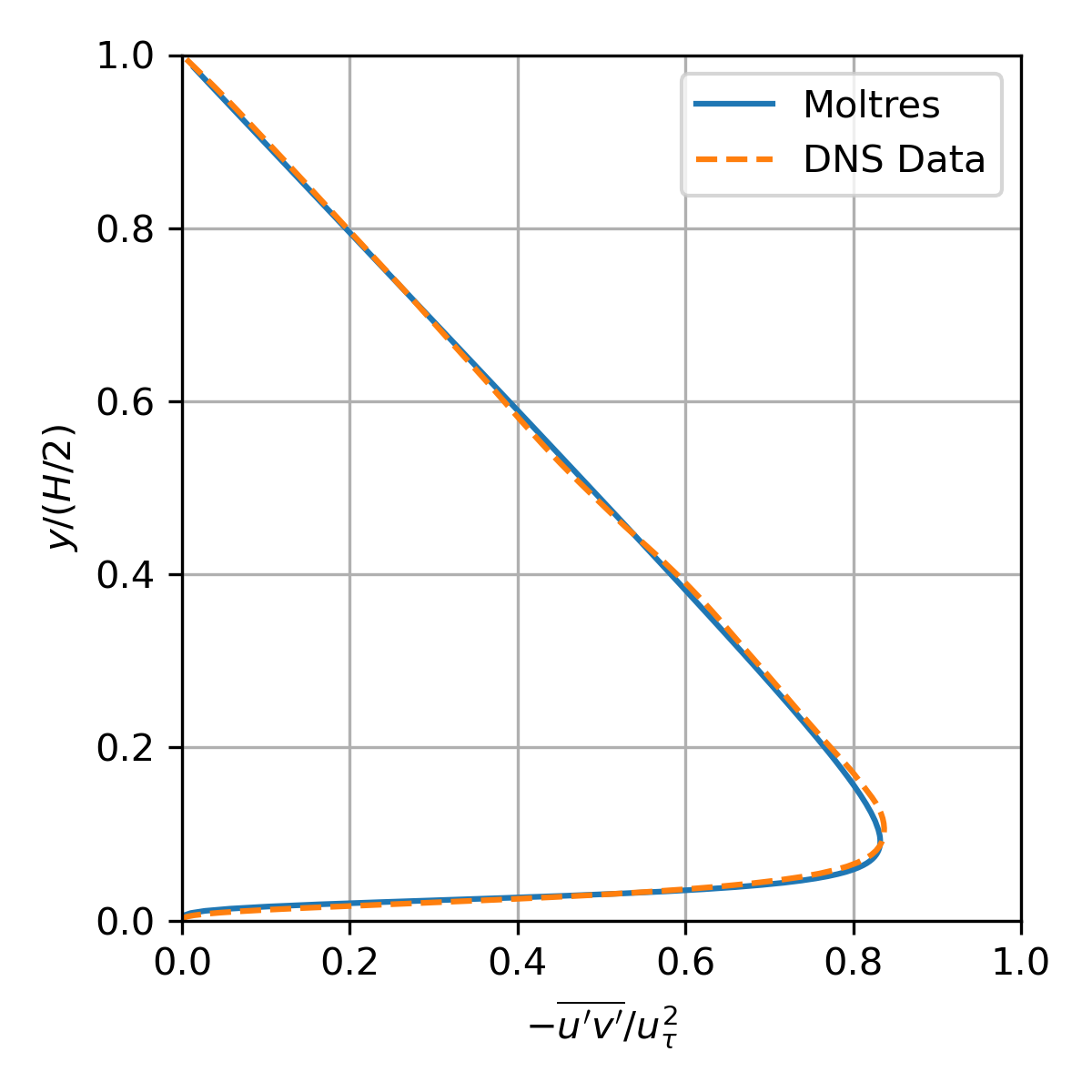
Figure 3: Normalized stress distribution across the channel.
Turbulent Pipe Flow Validation Test
The pipe flow test is based on the turbulent pipe flow experiment with by Laufer (1954). The Moltres input file for this problem may be found in moltres/problems/2023-basic-turbulence-cases/pipe-flow/.
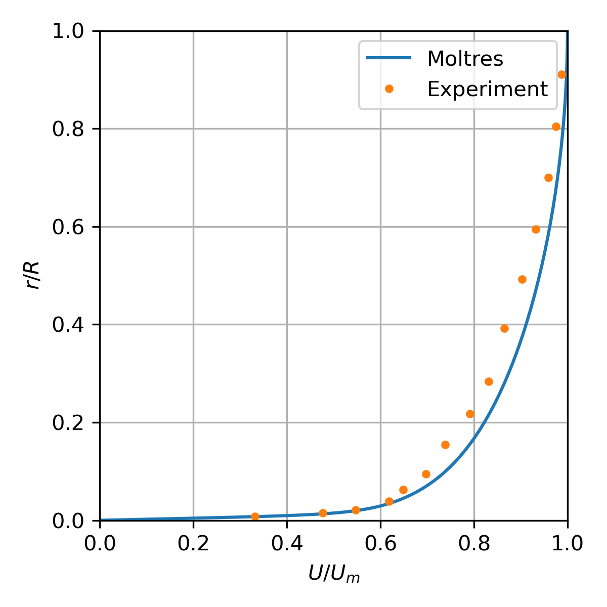
Figure 4: Normalized velocity distribution across the pipe.
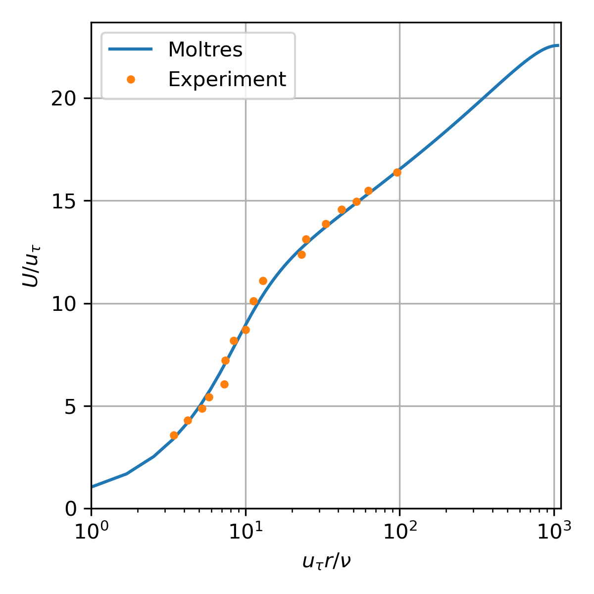
Figure 5: Dimensionless velocity vs dimensionless wall distance.
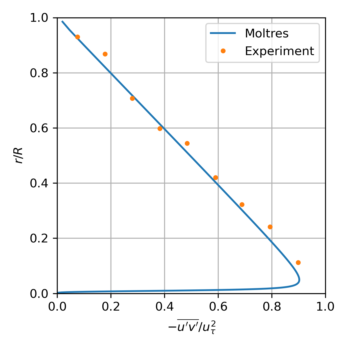
Figure 6: Normalized turbulent shear stress distribution across the channel.
Backward-Facing Step Flow Validation Test
The backward-facing step (BFS) flow test is based on the BFS flow experiment with by Driver and Seegmiller (1985). The Moltres input file for this problem may be found in moltres/problems/2023-basic-turbulence-cases/pipe-flow/. The SA model implementation in Moltres performs largely similarly to the reference SA model results provided on the Turbulence Modeling Resource website.
Table 3: Flow reattachment length estimates (normalized by step height )
| Reference experimental data | Reference SA model | Moltres |
|---|---|---|
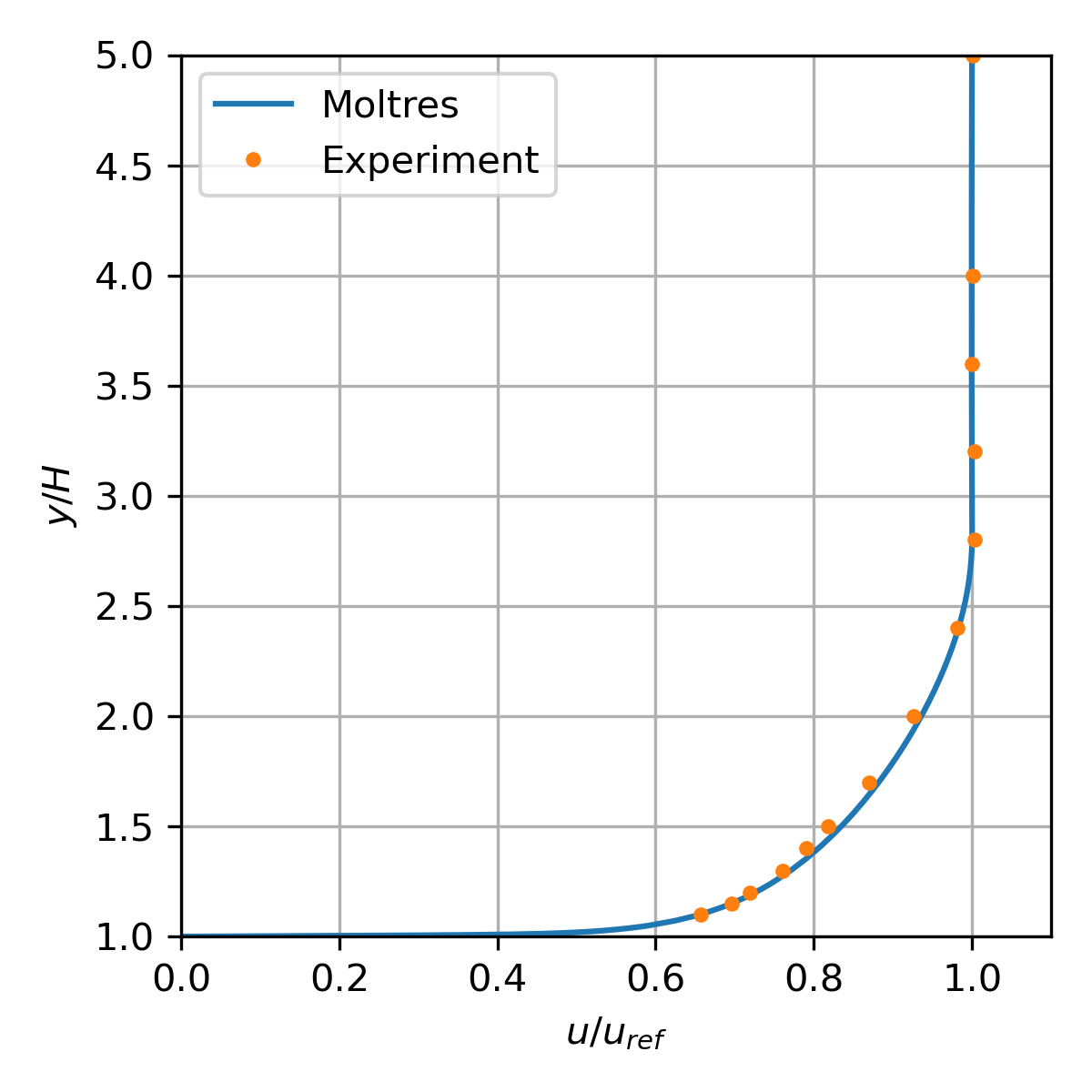
Figure 7: Normalized velocity distribution at equal -4 (upstream of step).
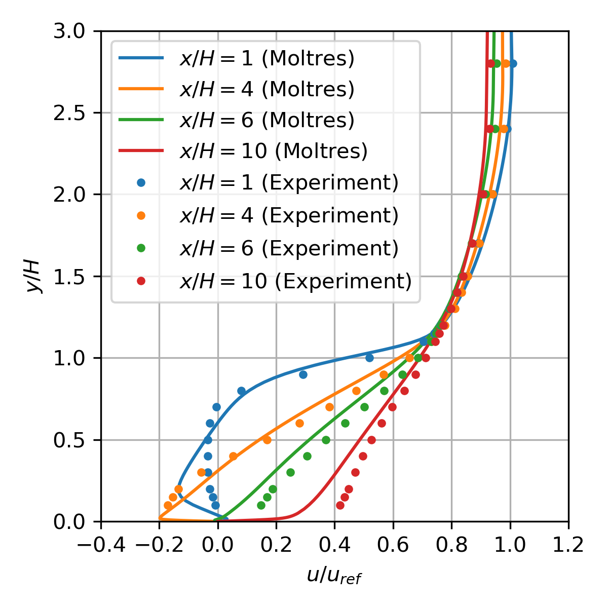
Figure 8: Normalized velocity distribution at various locations (downstream of step).
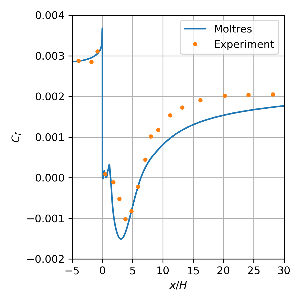
Figure 9: Skin friction coefficient along the bottom wall.
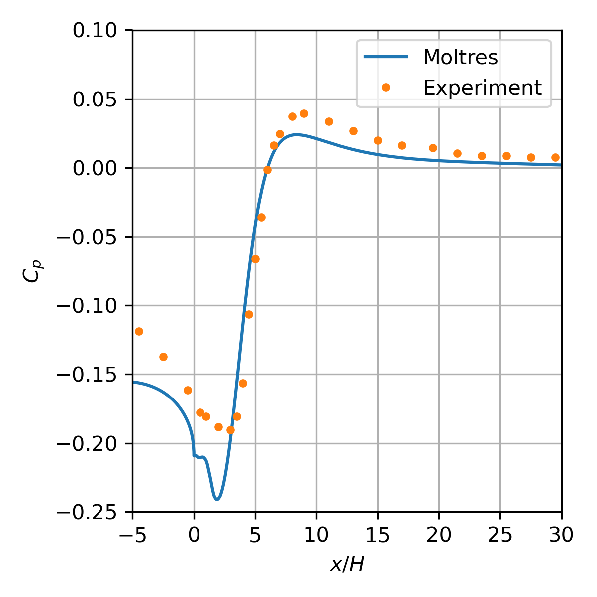
Figure 10: Skin pressure coefficient along the bottom wall.
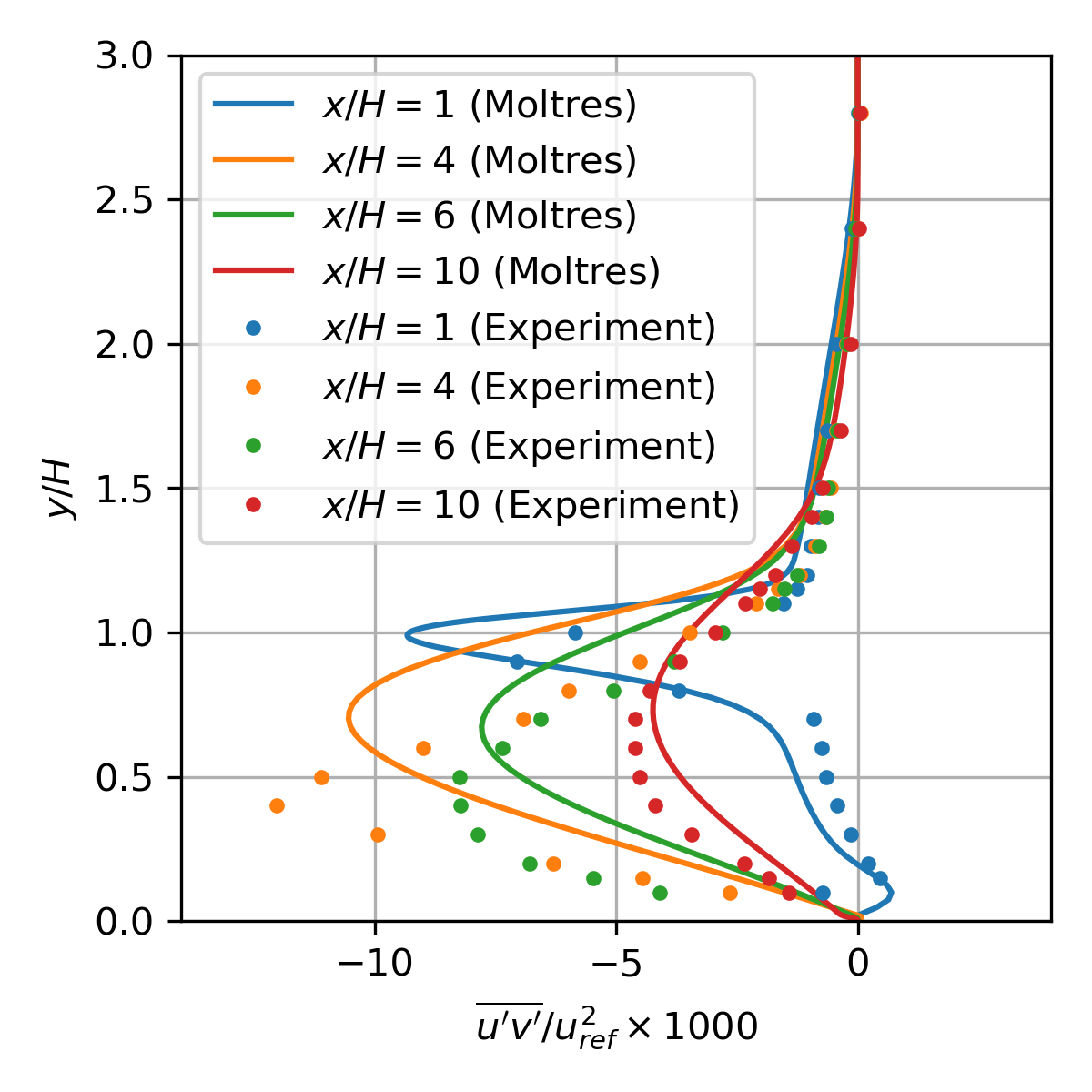
Figure 11: Normalized turbulent shear stress distribution at various locations (downstream of step).
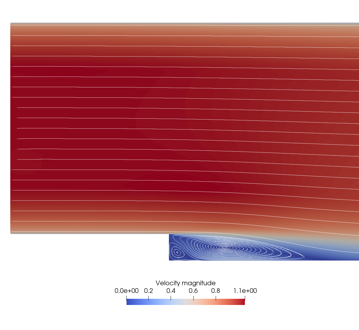
Figure 12: Close-up of the velocity magnitude and streamlines around the backward-facing step
References
- David M. Driver and H. Lee Seegmiller.
Features of a reattaching turbulent shear layer in divergent channelflow.
AIAA Journal, 23(2):163–171, February 1985.
URL: https://arc.aiaa.org/doi/10.2514/3.8890 (visited on 2022-01-17), doi:10.2514/3.8890.[Export]
- John Laufer.
The structure of turbulence in fully developed pipe flow.
Technical Report, National Bureau of Standards, January 1954.
NTRS Author Affiliations: NTRS Report/Patent Number: NACA-TR-1174 NTRS Document ID: 19930092199 NTRS Research Center: Legacy CDMS (CDMS).
URL: https://ntrs.nasa.gov/citations/19930092199 (visited on 2023-10-30).[Export]
- Robert D. Moser, John Kim, and Nagi N. Mansour.
Direct numerical simulation of turbulent channel flow up to Reτ=590.
Physics of Fluids, 11(4):943–945, April 1999.
URL: https://doi.org/10.1063/1.869966 (visited on 2023-10-30), doi:10.1063/1.869966.[Export]
- John Peterson, Alexander Lindsay, and Fande Kong.
Overview of the Incompressible Navier-Stokes simulation capabilities in the MOOSE Framework.
Advances in Engineering Software, 119:68–92, May 2018.
doi:10.1016/j.advengsoft.2018.02.004.[Export]
- P. Spalart and S. Allmaras.
A one-equation turbulence model for aerodynamic flows.
In 30th Aerospace Sciences Meeting and Exhibit. American Institute of Aeronautics and Astronautics, January 1992.
_eprint: https://arc.aiaa.org/doi/pdf/10.2514/6.1992-439.
URL: https://arc.aiaa.org/doi/abs/10.2514/6.1992-439 (visited on 2023-11-02), doi:10.2514/6.1992-439.[Export]